DIY Remote Controlled Tank using Arduino [A Must Do Robotic Project]
Hey guys, we are back with another cool DIY automaton. This is Quad Rail – A DIY Remote Controlled Tank. This is a 4 motors-driven Arduino -tracked automaton. I will be giving you complete details including the schematics, PCB files, and accomplished codes so that you can build one like this, or modify this and make your own version of it .
Arduino RC Tank In a Nutshell
Time Needed : 00 days 01 hours 30 minutes
here are the steps on How to make an RC Tank using Arduino in a nutshell .
- Tracked Robot Chassis Setup a Robot Chassis that is suitable for Off-Road Travel

- The Remote Controller for DIY Remote Controlled Tank Setup the remote control restrainer that we will be used for driving the automaton.

- Circuit Design and draw the schematics that we will be used for receiving data and driving the Robot.

- Assembilng the PCB once you get the PCB done, it ‘s time for us to solder all the components.

- Coding now, we can code our Arduino to receive the datum from the HC12 module, work and drive the automaton.

- Test Drive now you should be ready to take off. Have fun !

Materials
- Any Arduino Board with WiFi
- Motor Driver IC
- Battery
We will provide you with the design, code, circuit diagrams and links to buy your own automaton kit, chassis and the detector modules used in this project .
DIY Remote Controlled Tank Video Tutorial
Dont want to read the stallion stuff ? Dont worry, we have a video recording guide for you. Check out the below video .
We are superintendent excited to teach you everything you need to know about Arduino, robotics, and other playfulness DIY hobby projects. If you are a dependable fan of Arduino and you are truly interested in building amazing DIY projects, then this transmit is for you. thus make indisputable you subscribe to our channel by hitting the subscribe clitoris here. now, let ’ s catch started with the project .
Learning DIY Robotics has Never been so EASY!
DIY Robotics is a fun and easy thing you can learn within a matter of minutes if you have a proper guide. Do you want to learn Robotics but preceptor ’ thymine know where to start ? then THIS is for you. here, we will help you get started with DIY Robotics with easy-to-follow, 100 % FREE, bit-by-bit instructions starting from Robotics basics, parts of Robot, and then we will start complete bit-by-bit tutorials. here you will besides find an amazing collection of Robotics Project Tutorials from beginner flat to advanced for you to get started with DIY Robotics .
 Robotics Tutorial for Beginners Start Learning Robotics
Step 1 – Tracked Robot Chassis
I got this Tracked automaton chassis from Banggood. Unlike our previous Robots, this once has tracked wheels alternatively of the tires .
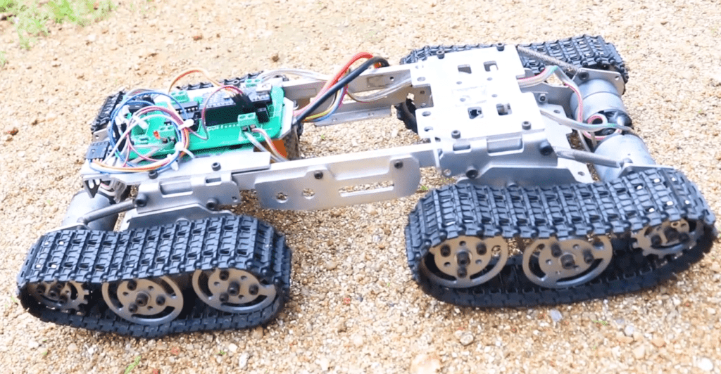 Tracked Robot Chassis – Tank Tread for Robotics This enables the RC Tank to travel over different kinds of terrains. It besides has a give suspension mechanism, for every wheel, so that the movement plate will mechanically adjust to obstacles and move over it .
Step 2 – The Remote Controller for DIY Remote Controlled Tank
Remote Controller Working
We will be controlling this Arduino tracked robot using an HC12 wireless module-based distant control. This wireless module chiefly contains an accelerometer, a joystick, and four switches. the microcontroller collects input from all the sensors and it will be concatenated into a long string of variables separated by a comma .
This line is sent to the HC12 radio receiver module which will transmit these signals over the air to all his HC12 wireless modules within its vicinity .
How to make Remote Controller?
It is very easy to make a outside control using an HC12 radio faculty. All you need is an Arduino, some sensors like Joystick, accelerometer or switches, and of course an HC12 radio receiver module. All you have to do is collect all the datum from the sensors, condition them and transmit them via the HC12 wireless module. You can either make your own version of it or follow our long-range remote control accountant tutorial and make the same one, I am using. Check out the below video recording .
Step 3 – Drawing the Circuit for DIY Remote Controlled Tank
Why not make a PCB for your Project?
Making a PCB for your DIY project is not hard nowadays. PCB helps to get rid of all messy wires and gorge and gives your project an amazing look. And it ’ s cool to make your own PCB for your visualize correctly ?
Read more: Unsuccessful takes of the Atlas robot
This is the circuit that we will be using on the Arduino RC Tank side . I used Altium couturier to draw the lap and purpose the PCB. It is a herculean instrument that can be used to design and create your own PCBs for your project angstrom well as building complex and multi-layer PCBs for industrial use. I will provide the associate to the release translation in the description. Make sure you check it out !
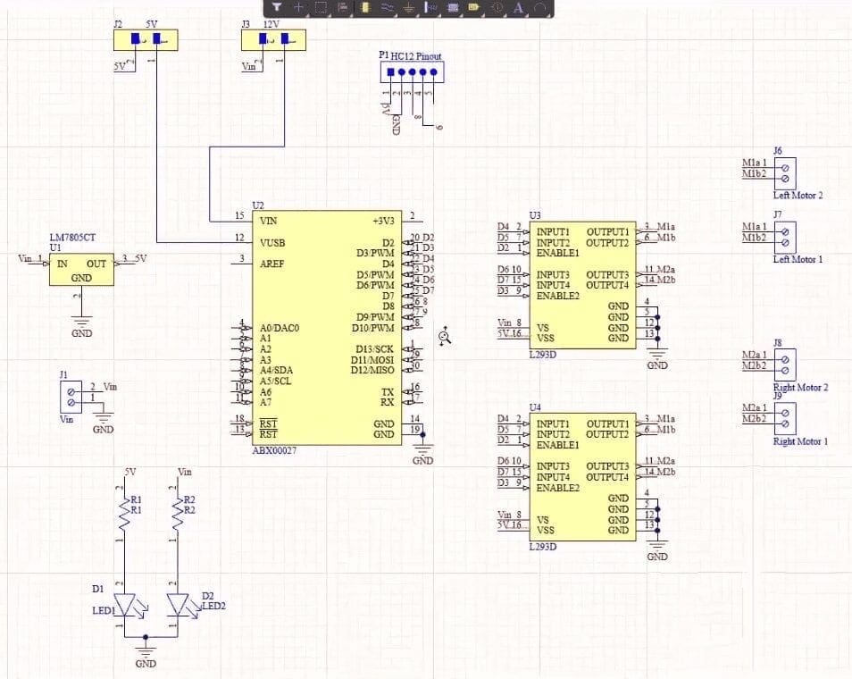 Arduino RC Tank Circuit The lap contains a end obstruct called Vin where we will be connecting remark exponent. You can connect a 9-volt battery, 12-volt lithium polymer battery or if you are planning on building a wire automaton you can use a 12-volt direct current adapter. This input power is then connected to a 7805 electric potential governor. This voltage regulator converts unregulated voltage between 7 to 32 volt to a steady 5-volt district of columbia exponent supply. This 5 volt is then fed to HC12 wireless module, L293D drive driver intelligence community, and to Arduino .
Or you can connect this voltage input directly to the Vin pin of Arduino. Since we have four motors in the DIY Remote Controlled Tank will be connecting two on either side. On the left, you will see forget motive 1 and left motive 2 and on the correctly side, you see right motor 1 and justly centrifugal 2 .
stimulation for the leave motors, that is input 1, input 2, and enable 1 will be connected to D4, D5, and D2 of the microcontroller. Whereas remark for properly motors, that is remark 3 input 4 and enable 2 will be connected to D6, D7, and D3 of the microcontroller .
Pin numbers 8 and 9 of Arduino will be connected to the pivot and Rx pin of the HC12 wireless module. These pins work as a software series interface using which we will be fetching the datum from the HC12 wireless module .
Arduino Tracked Robot Circuit Summary
Let me give you a short drumhead. This lap will collect all the datum from the HC12 radio receiver module of the remote control control, using the HC12 module connected to the Arduino of your DIY Remote Controlled Tank. This includes the detector values in a single wrinkle separated by a comma every 10 mississippi .
This data is then passed onto Arduino. The Arduino then processes the signals, separates them into unlike variables, and sends signals to the L293D motive driver intelligence community which will drive the motors .
Step 4 – Getting PCB Done
once the tour was finished, I designed a compact PCB using Altium, where I can fix all the components neatly. here you can see, routing is on both sides of the board, but components are placed on the clear side. And that ’ s done. now all you have to do is export the Gerber .
Odering PCB from PCBWay
I ordered PCB from PCBWay. Pcbway is a PCB manufacturer specializing in PCB prototyping, low-volume production, and neat and tidy PCB assembly. To regulate your PCB from the PCBWay, go to the PCBWay web site and filling in the basic board details in the instant holy order form .
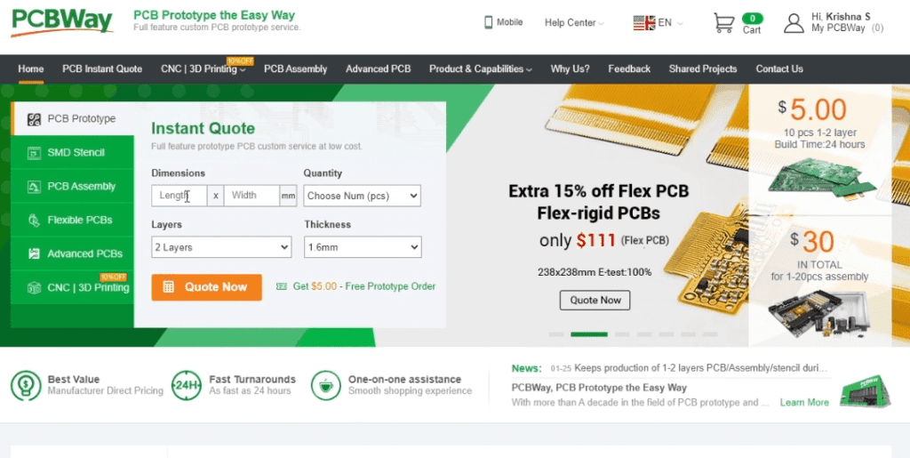 Ordering PCBs from PCBWay From there you will be directed to a phase where you can provide more detailed board details. Update your board information in the PCB specification screen. In the future screen, you should be able to upload your Gerber file and take it for review. Once the review is completed, all that is left is to add to the haul, make payment, and wait for your PCBs to arrive .
Step 5 – Assembling the PCB
once you get all the components and the PCB, it ’ mho time for you to solder them together. Solder all the components onto the dining table and make indisputable to check the mutual opposition of the components. After soldering the PCB looks like this .
Step 6 – Coding
now, let ’ s get gloomy to the software separate. here, I will be programming the board using our front-runner Arduino ide .
This is the code for your Arduino Tracked Robot .
Code
#include
#include

SoftwareSerial HC12(8, 9);

int lr, x, y;
int bf, motor1_speed, motor2_speed;
int mode;
String input;
int boundLow;
int boundHigh;
const char delimiter = ',';

void setup() {

  Serial.begin(9600);
  HC12.begin(9600);

  pinMode (2, OUTPUT);
  pinMode (3, OUTPUT);
  pinMode (4, OUTPUT);
  pinMode (5, OUTPUT);
  pinMode (6, OUTPUT);
  pinMode (7, OUTPUT);
}

void loop() {
  if (HC12.available())
  {
    input = HC12.readStringUntil('n');
    if (input.length() > 0)
    {
      Serial.println(input);

      boundLow = input.indexOf(delimiter);
      x = input.substring(0, boundLow).toInt();

      boundHigh = input.indexOf(delimiter, boundLow + 1);
      y = input.substring(boundLow + 1, boundHigh).toInt();

      boundLow = input.indexOf(delimiter, boundHigh + 1);
      bf = input.substring(boundHigh + 1, boundLow).toInt();

      boundHigh = input.indexOf(delimiter, boundLow + 1);
      lr = input.substring(boundLow + 1, boundHigh).toInt();

      mode = input.substring(boundHigh + 1).toInt();

      delay(10);
    }
    drive_robot(); //Comment this line and uncomment the next line for high speed
  }

}


void drive_robot()
{

  if ((bf <= 100) && (lr > 100) && (lr < 700))
  {
    left();
  }

  else if ((bf >= 700) && (lr > 100) && (lr < 700))
  {
    right();
  }

  else if ((lr <= 100) && (bf > 100) && (bf < 700))
  {
    backward();
  }

  else if ((lr >= 700) && (bf > 100) && (bf < 700))
  {
    forward();
  }

  else if ((lr <= 100) && (bf >= 700))
  {
    forward();
  }

  else if ((lr >= 700) && (bf >= 700))
  {
    backward();
  }
  else

  {
    stopp();
  }
}


void forward()
{
  analogWrite(2, 254);
  analogWrite(3, 254);

  digitalWrite(5, LOW);
  digitalWrite(4, HIGH);
  digitalWrite(7, LOW);
  digitalWrite(6, HIGH);
  Serial.println("Forward");
}

void backward()
{
  analogWrite(2, 254);
  analogWrite(3, 254);

  digitalWrite(5, HIGH);
  digitalWrite(4, LOW);
  digitalWrite(7, HIGH);
  digitalWrite(6, LOW);
  Serial.println("Backward");
}

void right()
{
  analogWrite(2, 200);
  analogWrite(3, 199);

  digitalWrite(5, LOW);
  digitalWrite(4, HIGH);
  digitalWrite(7, HIGH);
  digitalWrite(6, LOW);
  Serial.println("Right");
}
void left()
{
  analogWrite(2, 199);
  analogWrite(3, 200);

  digitalWrite(5, HIGH);
  digitalWrite(4, LOW);
  digitalWrite(7, LOW);
  digitalWrite(6, HIGH);
  Serial.println("Left");
}

void stopp()
{
  analogWrite(2, 0);
  analogWrite(3, 0);

  digitalWrite(5, LOW);
  digitalWrite(4, LOW);
  digitalWrite(6, LOW);
  digitalWrite(7, LOW);
  Serial.println("Stop");
}
DIY Remote Controlled Tank Code Explaination
The foremost thing to do is, include all the libraries that are required for our program. After that, we will define a software serial interface at pins 8 and 9. This is where we will be conducting the Tx and Rx pins of the HC12 wireless faculty. After that, we will declare some variables that will be used for separating and storing the variables .
In the setup serve, we will initiate the serial and software series communication. After that, we will declare all the pins arsenic output as will be connecting it to L293D motor driver ninety-nine for controlling the district of columbia motors .
In the loop topology routine, we will check for any entrance packets in the software serial interface at Pin 8 and 9. If there is any data coming through that software series interface, it will be stored in string variable input signal. After that, this will be broken down into separate detector values and will be stored in these variables. Once we have done that we will call the drive_robot function .
In the drive-robot function, we will provide conditions to drive the RC Tank the way we want depending on the value of the variables. There are five functions advancing, backward, left, correct, and intercept, which will turn on and off the pins that are connected to the L293D drive driver ninety-nine and control the motors .
Step 7 – Test Driving DIY Remote Controlled Tank
That ’ s it guys now all you have to do is select the right port and board and upload the code.
Read more: Unsuccessful takes of the Atlas robot
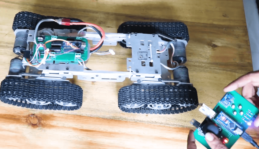 DIY Remote Controlled Tank using Arduino immediately you can exponent on the entire Arduino Tracked Robot and try moving the stick of the remote control accountant. If everything is working right you should be able to control our automaton using the distant restrainer .
You will find a fortune of amazing diy projects in our channel so make certain you check it out. If you have any questions regarding this project for any early projects do ask it in the comments .


