In one of our previous articles, we made many bots like the Self Balancing Robot, Automated Surface Disinfecting Robot, and the Obstacle Avoiding Robot. Do check those out if that sounds matter to to you .
Materials Required to Build Arduino Based Floor Cleaning Robot
As we have used identical generic components to build the hardware section of the vacuum cleaner robot, you should be able to find all of those in your local hobby storehouse. hera is the complete list of required corporeal along with the image of all the components.
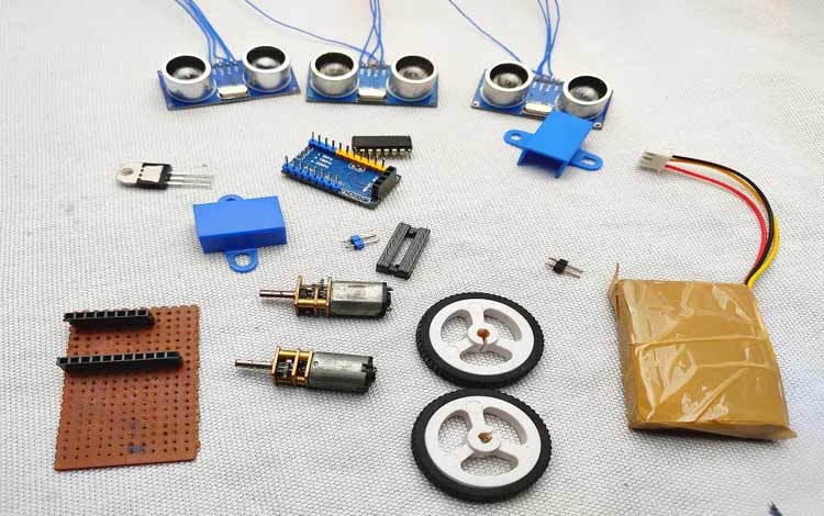
- Arduino Pro Mini – 1
- HC-SR04 Ultrasonic Module – 3
- L293D Motor Driver – 1
- 5Volt N20 Motors and Mounting Brackets – 2
- N20 Motor Wheels – 2
- Switch – 1
- LM7805 Voltage Regulator – 1
- 7.4V Lithium-Ion Battery – 1
- IR Module – 1
- Perfboard – 1
- Castor Wheel – 1
- MDF
- Generic Portable Vacuum Cleaner
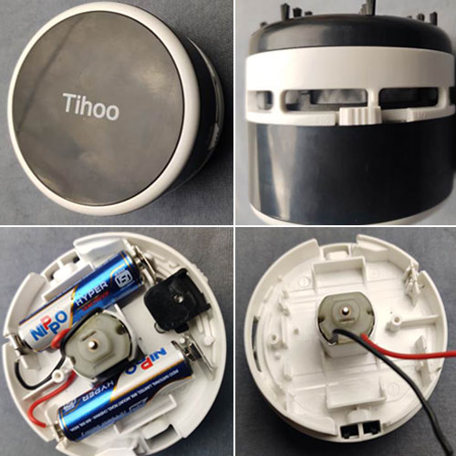
Portable Vacuum Cleaner
In the part necessity segment, we have talked about a portable vacuum cleaner, the images below show precisely that. It is a portable vacuum blank from amazon. This comes with a very simpleton mechanism. It has three parts in the bottom ( a little chamber for storing the dust, the center share includes the centrifugal, winnow, and the battery socket on the top ( there is a traverse or cap for the barrage ). It has a DC drive and a winnow. This motor is directly connected to 3V ( 2*1.5volt AA batteries ) via a childlike switch. As we are powering our automaton with a 7.4V battery, we will cut the connection from the internal battery and power it from the 5V power supply. so, we have removed all the unnecessary parts and alone the motor with two-wire stays. You can see that in the trope downstairs .
HC-SR04 Ultrasonic Sensor Module
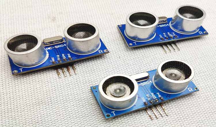
To detect the obstacles, we are using the popular HC-SR04 ultrasonic distance sensor or we can call it the obstacle avoidance sensors. The work is identical simple, first, the transmitter module sends an supersonic wave which travels through breeze, hits an obstacle, and bounces back and the receiver receives that roll. By calculating the time with Arduino, we can determine the distance. In a former article on Arduino Based Ultrasonic Distance Sensor project, we have discussed the working principle of this detector very thoroughly. You can check that out if you want to know more about the HC-SR04 supersonic distance detector faculty .
Floor Sensor (IR Sensor) for Staircase Detection
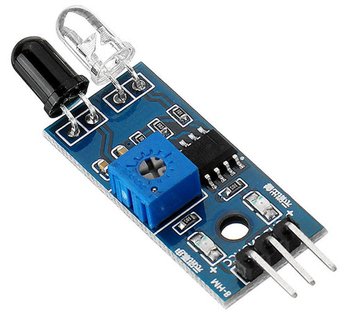
In the features section, we have talked about a sport where the automaton can detect staircases and can prevent itself from falling. To do that, we are using an IR Sensor. We will make an interface between the IR sensor and Arduino. The work of the IR Proximity Sensor is very simple, it has an IR LED and a photodiode, the IR LED emits IR light and if any obstacle comes in movement of this emit lightly, it will be reflected, and the reflected light will be detected by the photodiode. But the generate voltage from the reflection will be very low. To increase that, we can use an op-amp comparator, we can amplify and get output signal. An IR module has three pins – Vcc, labor, and output. normally, the end product goes low when an obstacle comes in front of the detector. so, we can use this to detect the floor. If for a rent second, we detect a high from the detector, we can stop the automaton, turn it back or do anything we want to prevent it from falling from the stairway. In a previous article, we have made a Breadboard interpretation of the IR Proximity Sensor Module and explained the working principle in details, you can check that out if you want to know more about this detector .
Circuit Diagram of Arduino Based Floor Cleaner Robot

We have three supersonic sensors that detect obstacles. sol, we need to connect all grounds of supersonic sensors and connected them to common anchor. besides, we connect all the three Vcc of the detector and get in touch that to the coarse VCC pin. future, we connect the trigger and echo pins to the PWM pins of the Arduino. We besides connect the VCC of the IR module to 5V and ground to the grind peg of Arduino, the output pin of the IR detector module goes to the digital fall D2 of the Arduino. For the centrifugal driver, we connect the two enable pins to 5v and besides the driver electric potential trap to 5V because we are using 5volt motors. In a previous article, we have made an Arduino Motor Driver Shield, you can check that out to learn more about L293D Motor Driver IC and its operations. The Arduino, Ultrasonic modules, centrifugal driver, and motors work on 5 Volt, the higher voltage will kill it and we are using the 7.4-volt battery, to convert that into 5 Volt, the LM7805 electric potential governor is used. Connect the vacuum cleaner directly to the independent tour .
Building the Circuit for Arduino Based Floor Cleaning Robot
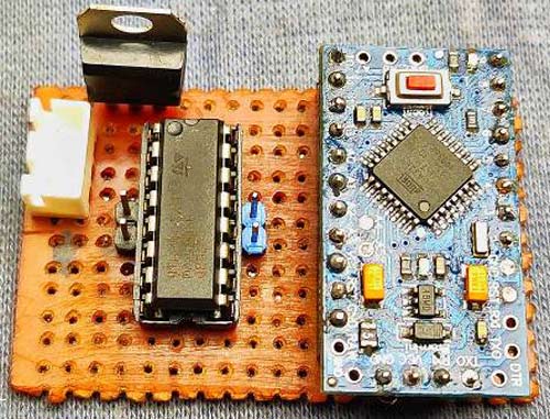
To solder every component together, first, I took a very small piece of scatter perfboard and topographic point every component according to the racing circuit diagram, and solder everything. This part is very dim-witted but do it with care. besides, we have used two female headers to place the Arduino professional mini. After completing the perfboard solder, we connect wires to supersonic modules and connect them to the represent pins, as shown in the conventional .
Building a Housing for Arduino Based Floor Cleaning Robot
In order to get some ideas about my automaton, I searched for vacuum cleaner robots on-line and got some images of round-shaped robots. indeed, I decided to build a round-shaped automaton. To build the pursuit and body of the automaton, I have plenty of options like foam sail, MDF, cardboard, etc. But I choose MDF because it is intemperate and has some water-repellent properties. If you are doing this, you can decide which material you will choose for your bot .
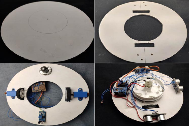
To build the automaton, I took the MDF sheet, then drew two circles with an 8 CM radius, and inside that lap, I have besides drawn another circle having a radius of 4 CM for fitting the vacuum clean. then I cut out the circles. besides, I have cut and removed appropriate pieces for the wheel way ( refer to the images for better understand ). finally, I made three modest holes for the beaver bicycle. The adjacent step is fitting the motors on the base using its brackets, besides place and fix the beaver wheel to its stead. After that, place the supersonic sensors to left, good, and center of the automaton. besides, connect the IR module to the downside of the automaton. Do n’t forget to add the switch on away. That ‘s all about building the automaton, if you are getting confused at this item, you can refer to the following images .
Read more: Technologies of the “BLACK MIRROR” series
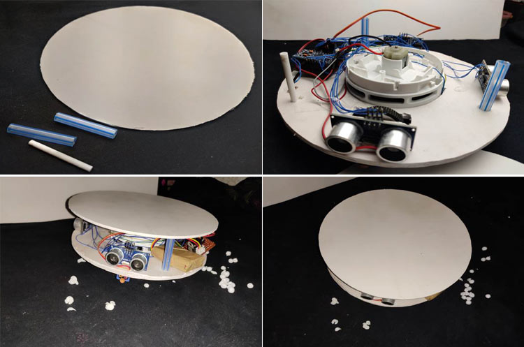
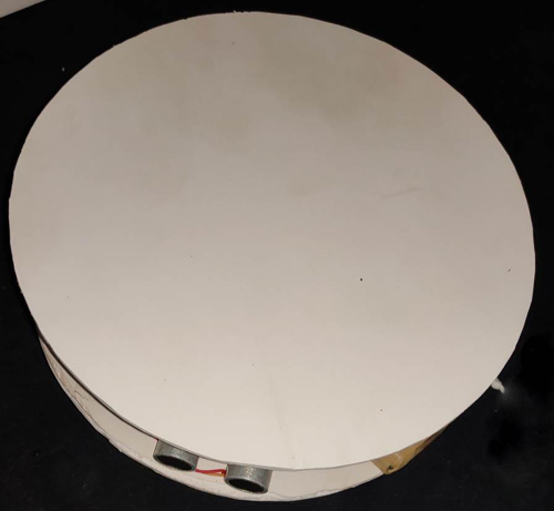
For the peak part, I have besides drawn a traffic circle of 11 CM in radius on the foam sheet and cut it. For the space between the peak and the bottom part, I had cut three 4 CM retentive pieces of a plastic tube. After that, I glued the plastic spacers on the bottomland separate and then I glued the top region. You can cover the side parts of the bot with formative or similar materials if you want .
Arduino Based Floor Cleaning Robot – Code
The complete code for this project is given at the end of the document. This Arduino code is like to the Arduino Based Ultrasonic Distance Sensor code, the only exchange is in the floor detection. In the follow lines, I am explaining how the code works. In this character, we are not using any extra libraries. Below we have described the code in a bit-by-bit manner. We are not using any extra libraries to decode the distance data from the HC-SR04 detector, because it ‘s identical simple. In the come lines, we described how. beginning, we need to define the Trigger Pin and Echo Pin for all three supersonic distance sensors which are connected to the Arduino display panel. In this undertaking, we have three Echo pins and three Trigger pins. note that 1 is the left detector, 2 is the front detector, and 3 is the right detector .
const int trigPin1 = 3;
const int echoPin1 = 5;
const int trigPin2 = 6;
const int echoPin2 =9;
const int trigPin3 = 10;
const int echoPin3 = 11;
int irpin =2;
then we defined variables for the distance which all are ( int ) type variables and for the duration, we chose to use ( long ). Again, we have three of each. besides, I have defined an integer for storing the condition of the movement, we will talk about it late in this section .
 long duration1;
 long duration2;
 long duration3;
int distanceleft;
int distancefront;
int distanceright;
int a=0;
following, in the frame-up section, we need to make all the position pins as input or output using the pinModes ( ) function. To send supersonic waves from the faculty, we need to enable trigger pin to high i.e all trip pins should define as OUTPUT. And to receive the repeat, we need to read the submit of echo pins so all echo pins should define as INPUT. besides, we enable the consecutive proctor for troubleshooting. To read the status of the IR-modules, I have defined the irpin as input signal .
pinMode(trigPin1, OUTPUT);
pinMode(trigPin2, OUTPUT);
pinMode(trigPin3, OUTPUT);
pinMode(echoPin1, INPUT);
pinMode(echoPin2, INPUT);
pinMode(echoPin3, INPUT);
 pinMode(irpin, INPUT);
And these digital pins are defined as OUTPUT for the input of the centrifugal driver .
pinMode(4, OUTPUT);
pinMode(7, OUTPUT);
pinMode(8, OUTPUT);
pinMode(12, OUTPUT);
In the main loop, we have three sections for three sensors. All the sections work the same but each for different sensors. In this section, we read the obstacle distance from each detector and storehouse it in each define integer. To read the distance, first, we have to make certain that the gun trigger pins are absolved, for that, we need to set the gun trigger peg to LOW for 2 µs. nowadays, for generating the supersonic wave, we need to turn the trigger peg HIGH for 10 µs. This will send the supersonic sound and with the assistant of the pulseIn ( ) function, we can read the travel fourth dimension, and memory that rate into the variable “ duration ”. This officiate has 2 parameters, the first one is the name of the echo pivot and for the second base one, you can write either HIGH or LOW. HIGH means that the pulseIn ( ) officiate will wait for the trap to go HIGH caused by the bounce sound wave and it will start count, then it will wait for the pin to go LOW when the voice beckon will end which will stop the count. This routine gives the length of the pulse in microseconds. For calculating the distance, we will multiply the duration by 0.034 ( speed of sound in air is 340m/s ) and divide it by 2 ( this is due to the back and away travel of the sound beckon ). last, we store the distance of each detector in corresponding integers .
digitalWrite(trigPin1, LOW);
delayMicroseconds(2);
digitalWrite(trigPin1, HIGH);
delayMicroseconds(10);
digitalWrite(trigPin1, LOW);
duration1 = pulseIn(echoPin1, HIGH);
distanceleft = duration1 * 0.034 / 2;
After getting the distance from each detector, we can control the motors with the help of an if statement therefore we control the apparent motion of the automaton. This is very bare, first, we gave an obstacle distance value, in this case, it is 15cm ( change this value as your wish ). then we gave conditions according to that value. For example, when an obstacle comes in front of the leave detector ( that means the distance of the bequeath detector should below or equals to 15 curium ) and the other two distances are high ( that means no obstacle is in movement of that ‘s sensors ), then with the serve of digital write function, we can drive the motors to properly. Later, I checked the condition of the IR detector. If the automaton is on the floor, the rate of the IR fall will be LOW, and if not, then the respect will be HIGH. then I stored that respect in the int s variable. We are going to control the automaton according to this condition .
This section of the Code is used to Move the Robot Forward and Backward :
if(s==HIGH)
  {
    digitalWrite(4, LOW);
    digitalWrite(7, HIGH);
    digitalWrite(8, LOW);
    digitalWrite(12, HIGH);
      delay(1000);
    a=1;
        }
But there is a problem with this method acting when the motor moves backward, the floor comes back and the bot will move forward, and it will repeat making the bot stick. To overcome that, we store a value ( 1 ) in int after understanding floor is not stage. We besides check this discipline for other movements .
After detecting the absence of the floor, the automaton will not move fore. alternatively, it will move left, this way, we can avoid the problem .
if ((a==0)&&(s==LOW)&&(distanceleft <= 15 && distancefront > 15 && distanceright <= 15) || (a==0)&&(s==LOW)&&(distanceleft > 15 && distancefront > 15 && distanceright > 15))
In the above condition. First, the automaton will check the floor condition and integer value. The bot will only move advancing if all conditions are satisfied .
now, we can write the commands for the centrifugal driver. This will drive the right-motor back and the left-motor forth, thereby turning the automaton to the Right .
This section of the Code is used to Move the Robot Right:
 digitalWrite(4, HIGH);
 digitalWrite(7, LOW);
 digitalWrite(8, HIGH);
 digitalWrite(12, LOW);
If the bot detects the floor is absent, the value changes to 1, and the bot will move to the leftover. After turning left, the value of ‘a ‘ changes to 0 from 1.
Read more: How To Hide a Litter Box
 if ((a==1) &&(s==LOW) ||(s==LOW) && (distanceleft <= 15 && distancefront <= 15 && distanceright > 15) || (s== LOW) && (distanceleft <= 15 && distancefront <= 15 && distanceright > 15) || (s==LOW) && (distanceleft <= 15 && distancefront > 15 && distanceright > 15) || (distanceleft <= 15 && distancefront > 15 && distanceright > 15))
  {
    digitalWrite(4, HIGH);
    digitalWrite(7, LOW);
    digitalWrite(8, LOW);
    digitalWrite(12, HIGH);
    delay(100);
    a=0;
  }
This section of the Code is used to Move the Robot Left:
 if ((s==LOW)&&(distanceleft > 15 && distancefront <= 15 && distanceright <= 15) ||(s==LOW)&& (distanceleft > 15 && distancefront > 15 && distanceright <= 15) ||(s==LOW)&& (distanceleft > 15 && distancefront <= 15 && distanceright > 15) )
    {
    digitalWrite(4, LOW);
    digitalWrite(7, HIGH);
    digitalWrite(8, HIGH);
    digitalWrite(12, LOW);
  }
That ‘s it for building Arduino based Smart Vacuum Cleaner Robot. The complete work of the project can be found in the video linked at the bottom of this page. If you have any questions, comment down below .


